,fit=pad/globalassets/logos/camlok/new/camlok-10.11.svg)
,fit=pad/globalassets/logos/cm/new/cm_color-10.11.svg)
,fit=pad/contentassets/1f4eac3541654db5a396d6c67f7ce0fb/crosby_red_rgb.png)
,fit=pad/globalassets/logos/dixie/new/dixie_industries_color-10.11.svg)
,fit=pad/globalassets/logos/dorner/new/dorner_color-10.11.svg)
,fit=pad/globalassets/logos/duff-norton/new/duff-norton_color-10.11.svg)
,fit=pad/globalassets/logos/garvey/new/garvey_color-10.11.svg)
,fit=pad/contentassets/8c25a81873f3447490ffdc9d9b53f5f5/kito_black.png)
,fit=pad/globalassets/logos/little-mule/new/little_mule_color-10.11.svg)
,fit=pad/globalassets/logos/magnetek/new/magnetek_wide_color-10.11.svg)
,fit=pad/globalassets/logos/pfaff/new/pfaff_color-10.11.svg)
,fit=pad/globalassets/logos/shaw-box/new/shaw-box_color-10.11.svg)
,fit=pad/globalassets/logos/stahl/new-by-cmco/stahl_color-10.11.svg)
,fit=pad/globalassets/logos/steerman/new/steerman_color-10.11.svg)
,fit=pad/globalassets/logos/unified/new/unified_color-10.11.svg)
,fit=pad/globalassets/logos/yale/new/yale-10.11.svg)
,fit=pad/globalassets/logos/budgit/new/budgit_hoists_color.png)
,fit=pad/globalassets/logos/chester/new/chester_hoist-10.11.svg)
,fit=pad/globalassets/logos/cm-et/cmet-color.svg)
 North America - EN
,fit=pad/globalassets/logos/camlok/new/camlok-10.11.svg)
,fit=pad/globalassets/logos/cm/new/cm_color-10.11.svg)
,fit=pad/contentassets/1f4eac3541654db5a396d6c67f7ce0fb/crosby_red_rgb.png)
,fit=pad/globalassets/logos/dixie/new/dixie_industries_color-10.11.svg)
,fit=pad/globalassets/logos/dorner/new/dorner_color-10.11.svg)
,fit=pad/globalassets/logos/duff-norton/new/duff-norton_color-10.11.svg)
,fit=pad/globalassets/logos/garvey/new/garvey_color-10.11.svg)
,fit=pad/contentassets/8c25a81873f3447490ffdc9d9b53f5f5/kito_black.png)
,fit=pad/globalassets/logos/little-mule/new/little_mule_color-10.11.svg)
,fit=pad/globalassets/logos/magnetek/new/magnetek_wide_color-10.11.svg)
,fit=pad/globalassets/logos/pfaff/new/pfaff_color-10.11.svg)
,fit=pad/globalassets/logos/shaw-box/new/shaw-box_color-10.11.svg)
,fit=pad/globalassets/logos/stahl/new-by-cmco/stahl_color-10.11.svg)
,fit=pad/globalassets/logos/steerman/new/steerman_color-10.11.svg)
,fit=pad/globalassets/logos/unified/new/unified_color-10.11.svg)
,fit=pad/globalassets/logos/yale/new/yale-10.11.svg)
,fit=pad/globalassets/logos/budgit/new/budgit_hoists_color.png)
,fit=pad/globalassets/logos/chester/new/chester_hoist-10.11.svg)
,fit=pad/globalassets/logos/cm-et/cmet-color.svg)
Synchronization Control System


Synchronization Control Systems provide an electrical solution to synchronizing actuators where mechanical shafting and coupling cannot be achieved. It is ideal for systems using multiple electric motors, and are designed to hold a tolerance that supports your application needs.
Documents
Need Assistance?
Not sure if this is the right product for your application, or need a custom solution? Contact us today for help from an expert.
Specifications
Specifications
Synchronization Controls Comparison Chart
| Control Type | Ease of Installation | Accuracy | Tolerance | System Flexibility | Longevity | Overall System Performance | Cost |
|---|---|---|---|---|---|---|---|
| Motor Starter |
★ ★ |
★ |
★ |
★ | ★ | ★ | $ |
| VFDs | ★ | ★★ | ★★ | ★★ | ★★★ | ★★ | $$ |
| Servo Motors | ★★★ | ★★★ | ★★★ | ★★★ | ★★ | ★★★ | $$$ |
| ★= Good ★★=Better ★★★=Best | |||||||
Standard Synchronization Control Methods
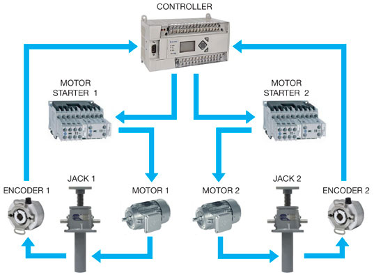
Method 1 - Synchronization Using Motor Starters
|
|---|
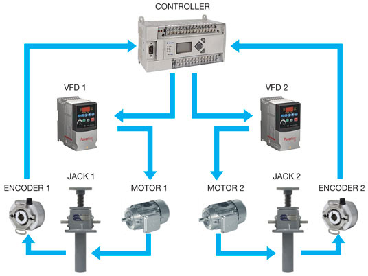
Method 2 - Synchronization Using Variable Frequency Drives (VFD)
|
|---|
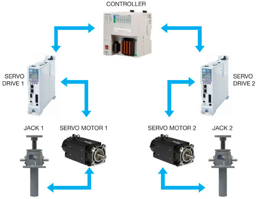
Method 3 - Synchronization Using Servo Motors With Absolute Encoders
|
|---|
Documents
Documents
Brochures & Catalogs
Related Products